> ## Documentation Index
> Fetch the complete documentation index at: https://docs.altnautica.com/llms.txt
> Use this file to discover all available pages before exploring further.
# Your First Mission
> Plan a survey mission, set altitude and overlap, upload to the FC, and execute in Auto mode.
**Alpha stage.** This guide is based on bench-level testing only. Some steps may change as we validate on real hardware. Check back once we ship a stable release.
## What You Will Do
This guide walks you through planning an automated survey mission in ADOS Mission Control. You will define an area, generate a survey grid pattern, set flight parameters, upload the mission to your flight controller, execute it in Auto mode, and download logs afterward.
By the end, your drone will have flown a complete survey pattern autonomously.
## Prerequisites
* Mission Control running and connected to your FC (see [Quickstart](/getting-started/quickstart-mission-control))
* A drone with GPS lock (3D Fix, 8+ satellites)
* An ArduPilot, PX4, or iNav flight controller (mission planning works over MAVLink for ArduPilot and PX4, and over MSP for iNav)
* A battery with at least 80% charge
* An open outdoor area for the flight
You can plan missions without a connected FC. The planner works offline. Upload the mission when you are ready to fly.
## Planning the Mission
Click the **Plan** tab in the main navigation. You will see a map view with your current GPS position (if connected to a FC with GPS) or a default location.
The left panel shows the mission tools: waypoint list, pattern generators, settings, and import/export.
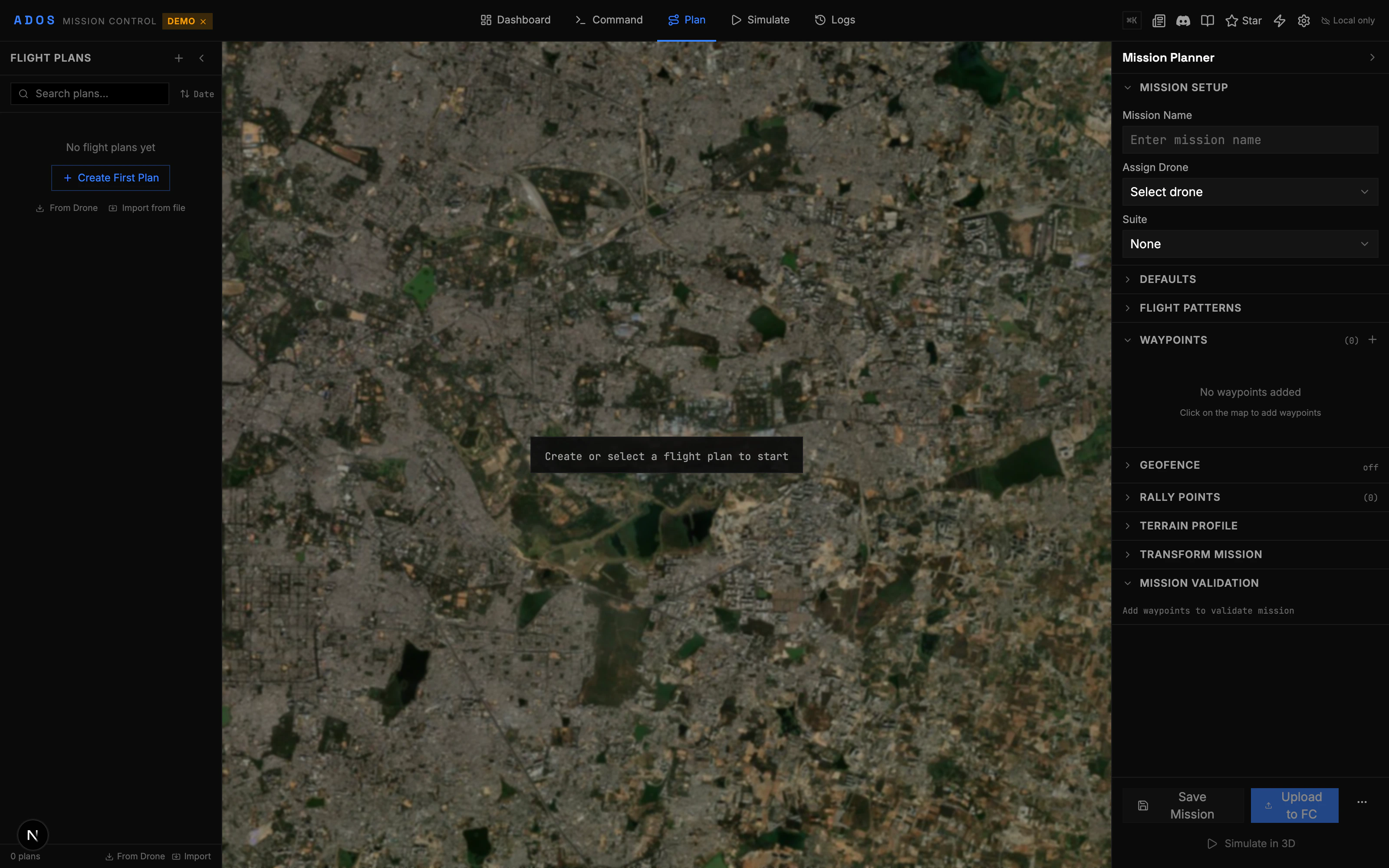 You have two options:
**Option A: Draw on the map**
1. Click the **Draw Polygon** tool in the toolbar
2. Click on the map to place polygon vertices around the area you want to survey
3. Close the polygon by clicking the first vertex or double-clicking
**Option B: Import a boundary**
1. Click **Import** in the tools panel
2. Load a KML, GeoJSON, or CSV file with your survey boundary
3. The polygon appears on the map
The polygon defines where the drone will fly. Make it slightly larger than your actual area of interest to account for camera overlap at the edges.
With the polygon selected, open the **Pattern Generator** panel and choose **Survey Grid**.
The survey grid generator creates a lawnmower pattern that covers the entire polygon. Configure these settings:
| Setting | What It Controls | Recommended Start |
| ------------------- | ---------------------------------------- | --------------------------------------- |
| **Altitude** | Flight height above ground | 50m for general mapping, 30m for detail |
| **Speed** | Ground speed during survey legs | 5-8 m/s |
| **Overlap (front)** | Image overlap along the flight direction | 75% |
| **Overlap (side)** | Image overlap between adjacent legs | 65% |
| **Angle** | Grid rotation angle | 0° (north-south legs) or auto-optimize |
| **Camera trigger** | How the camera fires | Distance-based or time-based |
Click **Generate**. The pattern appears on the map as a series of parallel waypoints.
You have two options:
**Option A: Draw on the map**
1. Click the **Draw Polygon** tool in the toolbar
2. Click on the map to place polygon vertices around the area you want to survey
3. Close the polygon by clicking the first vertex or double-clicking
**Option B: Import a boundary**
1. Click **Import** in the tools panel
2. Load a KML, GeoJSON, or CSV file with your survey boundary
3. The polygon appears on the map
The polygon defines where the drone will fly. Make it slightly larger than your actual area of interest to account for camera overlap at the edges.
With the polygon selected, open the **Pattern Generator** panel and choose **Survey Grid**.
The survey grid generator creates a lawnmower pattern that covers the entire polygon. Configure these settings:
| Setting | What It Controls | Recommended Start |
| ------------------- | ---------------------------------------- | --------------------------------------- |
| **Altitude** | Flight height above ground | 50m for general mapping, 30m for detail |
| **Speed** | Ground speed during survey legs | 5-8 m/s |
| **Overlap (front)** | Image overlap along the flight direction | 75% |
| **Overlap (side)** | Image overlap between adjacent legs | 65% |
| **Angle** | Grid rotation angle | 0° (north-south legs) or auto-optimize |
| **Camera trigger** | How the camera fires | Distance-based or time-based |
Click **Generate**. The pattern appears on the map as a series of parallel waypoints.
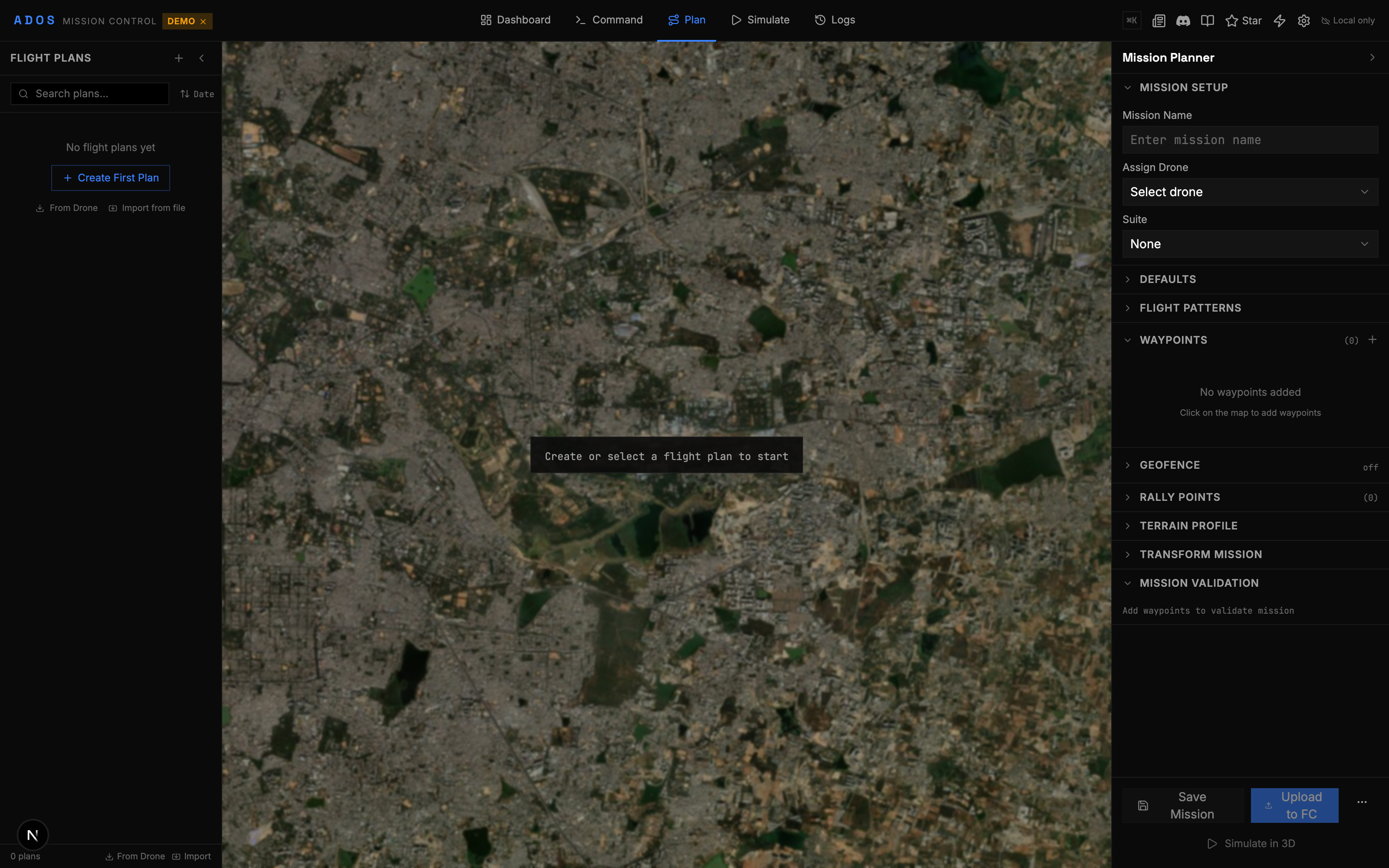 The auto-optimize angle option rotates the grid to minimize the number of turns. This saves battery and flight time. For rectangular fields, the optimal angle usually aligns with the longest edge.
After generating the pattern, the tools panel shows:
* **Total waypoints:** Number of mission items
* **Total distance:** Flight path length in meters
* **Estimated time:** Based on your speed setting
* **Leg count:** Number of parallel survey legs
* **Photo count:** Estimated images based on overlap and altitude
Scroll through the waypoint list to inspect individual points. Each waypoint shows:
* Sequence number
* Latitude/longitude
* Altitude (relative to home or terrain)
* Command type (NAV\_WAYPOINT, DO\_SET\_CAM\_TRIGG\_DIST, etc.)
Click any waypoint in the list to highlight it on the map. Click a waypoint on the map to select it in the list.
A mission needs a takeoff command at the beginning and a return-to-launch (RTL) at the end.
1. Click **Add Takeoff** at the top of the waypoint list. Set the takeoff altitude (typically the same as your survey altitude).
2. Click **Add RTL** at the bottom of the list.
The complete mission sequence is now:
```
1. TAKEOFF to 50m
2-N. Survey waypoints (NAV_WAYPOINT + camera triggers)
N+1. RTL (return to launch and land)
```
A geofence defines a boundary the drone cannot cross. If the drone reaches the fence, the FC triggers a failsafe action (RTL, land, or brake).
1. Click the **Geofence** tool
2. Draw a polygon larger than your survey area (give 50-100m buffer)
3. Set the maximum altitude (100m is a common default)
4. Set the breach action (RTL recommended)
On ArduPilot, this uses the `FENCE_ENABLE`, `FENCE_TYPE`, and `FENCE_ACTION` parameters. Mission Control handles the parameter mapping automatically.
Rally points are alternate landing locations. If the drone triggers RTL and cannot reach home (wind, obstacles), it goes to the nearest rally point instead.
1. Click the **Rally Points** tool
2. Click on the map to place rally points at safe landing spots
3. Set the altitude for each point (the drone approaches at this altitude before descending)
Click **Validate** in the tools panel. The validator checks for:
* Missing takeoff command
* Missing RTL or land command
* Waypoints outside the geofence
* Altitude violations (too low, too high)
* Speed violations
* Duplicate waypoints
* Distance between waypoints (too close or too far)
Errors appear in red. Warnings appear in yellow. Fix any errors before uploading. Warnings are advisory.
## Uploading the Mission
Make sure your flight controller is connected (green status indicator in the top bar). The FC must be online for mission upload.
Click **Upload Mission** in the tools panel.
Mission Control sends the mission items to the FC using the MAVLink mission protocol:
1. Sends `MISSION_COUNT` with the total number of items
2. FC requests each item with `MISSION_REQUEST_INT`
3. GCS sends each `MISSION_ITEM_INT`
4. FC sends `MISSION_ACK` when all items are received
A progress bar shows the upload. Typical upload time: 1-5 seconds depending on mission size and connection speed.
Mission Control uses `MISSION_ITEM_INT` (message 73) for all mission uploads. This is the modern format with integer latitude/longitude (1e7 scaling) for higher precision. Older `MISSION_ITEM` (message 39) is supported for downloads but not used for uploads.
After upload, click **Download Mission** to read the mission back from the FC. Compare the downloaded mission with your plan. The waypoints, altitudes, and commands should match exactly.
This step catches rare transmission errors. If anything looks wrong, re-upload.
## Executing the Mission
Run the same pre-flight checks from the [Your First Flight](/getting-started/your-first-flight) guide:
* GPS 3D Fix, 8+ satellites
* Battery above 80%
* Pre-arm messages clear
* Geofence parameters set if you defined a geofence
* Wind conditions acceptable for your drone
Arm the drone in Stabilize or Loiter mode first. Do not arm directly in Auto mode for your first mission. This gives you a chance to take off manually and verify flight behavior before handing over to autonomy.
Click **Arm** and confirm.
Take off to a safe hover altitude (3-5 meters). Verify the drone is stable and responsive.
Click the mode selector and choose **Auto**. The drone will immediately start flying toward the first waypoint.
What happens:
1. The drone climbs to the mission's first waypoint altitude
2. It flies to waypoint 1 (the takeoff point, already at altitude)
3. It begins the survey pattern, flying leg by leg
4. Camera triggers fire at the configured interval
5. At the last waypoint, it executes the RTL command
6. It flies back to the launch point and lands
The auto-optimize angle option rotates the grid to minimize the number of turns. This saves battery and flight time. For rectangular fields, the optimal angle usually aligns with the longest edge.
After generating the pattern, the tools panel shows:
* **Total waypoints:** Number of mission items
* **Total distance:** Flight path length in meters
* **Estimated time:** Based on your speed setting
* **Leg count:** Number of parallel survey legs
* **Photo count:** Estimated images based on overlap and altitude
Scroll through the waypoint list to inspect individual points. Each waypoint shows:
* Sequence number
* Latitude/longitude
* Altitude (relative to home or terrain)
* Command type (NAV\_WAYPOINT, DO\_SET\_CAM\_TRIGG\_DIST, etc.)
Click any waypoint in the list to highlight it on the map. Click a waypoint on the map to select it in the list.
A mission needs a takeoff command at the beginning and a return-to-launch (RTL) at the end.
1. Click **Add Takeoff** at the top of the waypoint list. Set the takeoff altitude (typically the same as your survey altitude).
2. Click **Add RTL** at the bottom of the list.
The complete mission sequence is now:
```
1. TAKEOFF to 50m
2-N. Survey waypoints (NAV_WAYPOINT + camera triggers)
N+1. RTL (return to launch and land)
```
A geofence defines a boundary the drone cannot cross. If the drone reaches the fence, the FC triggers a failsafe action (RTL, land, or brake).
1. Click the **Geofence** tool
2. Draw a polygon larger than your survey area (give 50-100m buffer)
3. Set the maximum altitude (100m is a common default)
4. Set the breach action (RTL recommended)
On ArduPilot, this uses the `FENCE_ENABLE`, `FENCE_TYPE`, and `FENCE_ACTION` parameters. Mission Control handles the parameter mapping automatically.
Rally points are alternate landing locations. If the drone triggers RTL and cannot reach home (wind, obstacles), it goes to the nearest rally point instead.
1. Click the **Rally Points** tool
2. Click on the map to place rally points at safe landing spots
3. Set the altitude for each point (the drone approaches at this altitude before descending)
Click **Validate** in the tools panel. The validator checks for:
* Missing takeoff command
* Missing RTL or land command
* Waypoints outside the geofence
* Altitude violations (too low, too high)
* Speed violations
* Duplicate waypoints
* Distance between waypoints (too close or too far)
Errors appear in red. Warnings appear in yellow. Fix any errors before uploading. Warnings are advisory.
## Uploading the Mission
Make sure your flight controller is connected (green status indicator in the top bar). The FC must be online for mission upload.
Click **Upload Mission** in the tools panel.
Mission Control sends the mission items to the FC using the MAVLink mission protocol:
1. Sends `MISSION_COUNT` with the total number of items
2. FC requests each item with `MISSION_REQUEST_INT`
3. GCS sends each `MISSION_ITEM_INT`
4. FC sends `MISSION_ACK` when all items are received
A progress bar shows the upload. Typical upload time: 1-5 seconds depending on mission size and connection speed.
Mission Control uses `MISSION_ITEM_INT` (message 73) for all mission uploads. This is the modern format with integer latitude/longitude (1e7 scaling) for higher precision. Older `MISSION_ITEM` (message 39) is supported for downloads but not used for uploads.
After upload, click **Download Mission** to read the mission back from the FC. Compare the downloaded mission with your plan. The waypoints, altitudes, and commands should match exactly.
This step catches rare transmission errors. If anything looks wrong, re-upload.
## Executing the Mission
Run the same pre-flight checks from the [Your First Flight](/getting-started/your-first-flight) guide:
* GPS 3D Fix, 8+ satellites
* Battery above 80%
* Pre-arm messages clear
* Geofence parameters set if you defined a geofence
* Wind conditions acceptable for your drone
Arm the drone in Stabilize or Loiter mode first. Do not arm directly in Auto mode for your first mission. This gives you a chance to take off manually and verify flight behavior before handing over to autonomy.
Click **Arm** and confirm.
Take off to a safe hover altitude (3-5 meters). Verify the drone is stable and responsive.
Click the mode selector and choose **Auto**. The drone will immediately start flying toward the first waypoint.
What happens:
1. The drone climbs to the mission's first waypoint altitude
2. It flies to waypoint 1 (the takeoff point, already at altitude)
3. It begins the survey pattern, flying leg by leg
4. Camera triggers fire at the configured interval
5. At the last waypoint, it executes the RTL command
6. It flies back to the launch point and lands
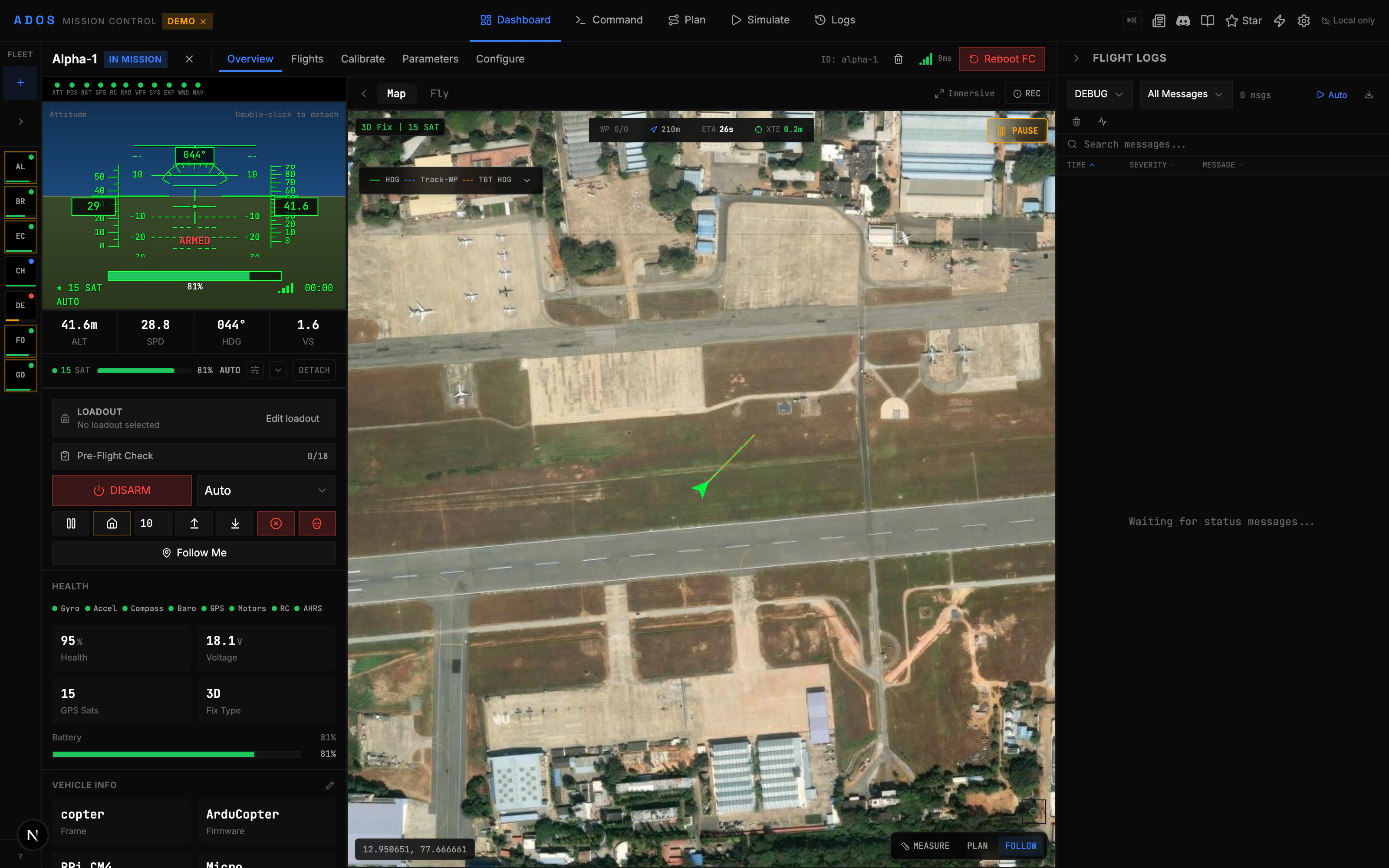 While the mission runs, watch:
* **Progress:** The active waypoint is highlighted on the map. Completed legs change color.
* **Altitude:** Verify the drone is holding the target altitude.
* **Battery:** Watch voltage sag under load. If you see voltage dropping faster than expected, be ready to abort.
* **Ground speed:** Should be close to your configured speed.
* **Camera triggers:** The mission item count increments as camera commands execute.
Keep your finger on the mode switch. If anything goes wrong, switch to **Loiter** to stop, or **RTL** to bring it home.
The drone will auto-land at the launch point (RTL) and auto-disarm.
If you need to abort mid-mission:
* Switch to **Loiter**: Drone stops and holds position
* Switch to **RTL**: Drone comes home
* Switch to **Land**: Drone lands at current position
* Click **Disarm** (emergency only, cuts motors immediately)
Only use emergency disarm (cutting motors) as an absolute last resort. The drone will fall from whatever altitude it is at. Use RTL or Land for controlled returns.
## Other Pattern Types
The survey grid is one of seven pattern generators in Mission Control. Here are the others:
| Pattern | Use Case | How It Works |
| -------------------- | -------------------------------- | --------------------------------------------------------------------------------- |
| **Survey Grid** | Area mapping, photogrammetry | Parallel legs covering a polygon (crosshatch double-pass option for high overlap) |
| **Orbit** | Point-of-interest coverage | Circle around a center point at a set radius |
| **Corridor Scan** | Road, pipeline, or river mapping | Parallel legs along a line/path |
| **Expanding Square** | SAR from a last-known position | Square spiral outward from a datum point |
| **Sector Search** | SAR over a wedge area | Pie-slice legs radiating from a datum point |
| **Parallel Track** | SAR sweep of a wide area | Evenly spaced parallel legs across a region |
| **Structure Scan** | Facade and 3D structure capture | Multi-altitude orbit with the camera pointed inward |
Each pattern has its own configuration panel. The workflow is the same: define the area, configure parameters, generate, validate, upload.
## Saving and Loading Missions
### Save to File
Click **Export** to save your mission as:
* **QGC WPL 110**: Standard MAVLink waypoint format. Compatible with QGroundControl, Mission Planner, and other GCS tools.
* **KML**: Google Earth format. Good for sharing with non-drone people.
* **CSV**: Spreadsheet format. One row per waypoint.
### Load from File
Click **Import** to load a mission from any of the above formats. You can also import boundaries from KML or GeoJSON for the polygon tools.
### Mission Library
If you have cloud features enabled (Convex backend), missions are saved to the mission library in the cloud. You can browse, duplicate, and re-use past missions. This is useful for recurring survey jobs where you fly the same pattern regularly.
## Simulation
Before flying a real mission, you can simulate it.
1. Go to the **Simulate** tab
2. Select your uploaded mission
3. Click **Play**
The simulator shows:
* 3D visualization of the flight path on terrain
* Camera trigger points marked on the map
* Estimated timing for each leg
* Altitude profile along the route
* Terrain clearance warnings if the flight path gets too close to the ground
This is not a physics simulation (use SITL for that). It is a geometric visualization that helps you verify your mission makes sense before committing a battery to it.
## Tips for Better Surveys
**Altitude matters.** Lower altitude = higher resolution photos but more flight legs and longer mission time. 50m is a good balance for general mapping. 25-30m for detailed inspection. 80-100m for large area overview.
**Overlap is important.** 75% front overlap and 65% side overlap is the starting point for photogrammetry. If your processing software struggles to stitch images, increase side overlap to 70-75%.
**Wind check.** Survey missions fly at constant speed. Headwind legs are slower (use more battery). Tailwind legs are faster. Plan the grid angle perpendicular to the wind direction when possible, so wind is a crosswind on the survey legs.
**Battery budget.** Plan for 70% of your battery capacity, not 100%. Keep 30% as margin for wind, unexpected maneuvers, and RTL. Check your estimated flight time against your battery's known endurance.
## Next Steps
Deep dive into all 7 pattern types with configuration guides.
Set up safety boundaries and alternate landing points.
Run 3D mission simulations before flying.
Import and export missions in multiple formats.
While the mission runs, watch:
* **Progress:** The active waypoint is highlighted on the map. Completed legs change color.
* **Altitude:** Verify the drone is holding the target altitude.
* **Battery:** Watch voltage sag under load. If you see voltage dropping faster than expected, be ready to abort.
* **Ground speed:** Should be close to your configured speed.
* **Camera triggers:** The mission item count increments as camera commands execute.
Keep your finger on the mode switch. If anything goes wrong, switch to **Loiter** to stop, or **RTL** to bring it home.
The drone will auto-land at the launch point (RTL) and auto-disarm.
If you need to abort mid-mission:
* Switch to **Loiter**: Drone stops and holds position
* Switch to **RTL**: Drone comes home
* Switch to **Land**: Drone lands at current position
* Click **Disarm** (emergency only, cuts motors immediately)
Only use emergency disarm (cutting motors) as an absolute last resort. The drone will fall from whatever altitude it is at. Use RTL or Land for controlled returns.
## Other Pattern Types
The survey grid is one of seven pattern generators in Mission Control. Here are the others:
| Pattern | Use Case | How It Works |
| -------------------- | -------------------------------- | --------------------------------------------------------------------------------- |
| **Survey Grid** | Area mapping, photogrammetry | Parallel legs covering a polygon (crosshatch double-pass option for high overlap) |
| **Orbit** | Point-of-interest coverage | Circle around a center point at a set radius |
| **Corridor Scan** | Road, pipeline, or river mapping | Parallel legs along a line/path |
| **Expanding Square** | SAR from a last-known position | Square spiral outward from a datum point |
| **Sector Search** | SAR over a wedge area | Pie-slice legs radiating from a datum point |
| **Parallel Track** | SAR sweep of a wide area | Evenly spaced parallel legs across a region |
| **Structure Scan** | Facade and 3D structure capture | Multi-altitude orbit with the camera pointed inward |
Each pattern has its own configuration panel. The workflow is the same: define the area, configure parameters, generate, validate, upload.
## Saving and Loading Missions
### Save to File
Click **Export** to save your mission as:
* **QGC WPL 110**: Standard MAVLink waypoint format. Compatible with QGroundControl, Mission Planner, and other GCS tools.
* **KML**: Google Earth format. Good for sharing with non-drone people.
* **CSV**: Spreadsheet format. One row per waypoint.
### Load from File
Click **Import** to load a mission from any of the above formats. You can also import boundaries from KML or GeoJSON for the polygon tools.
### Mission Library
If you have cloud features enabled (Convex backend), missions are saved to the mission library in the cloud. You can browse, duplicate, and re-use past missions. This is useful for recurring survey jobs where you fly the same pattern regularly.
## Simulation
Before flying a real mission, you can simulate it.
1. Go to the **Simulate** tab
2. Select your uploaded mission
3. Click **Play**
The simulator shows:
* 3D visualization of the flight path on terrain
* Camera trigger points marked on the map
* Estimated timing for each leg
* Altitude profile along the route
* Terrain clearance warnings if the flight path gets too close to the ground
This is not a physics simulation (use SITL for that). It is a geometric visualization that helps you verify your mission makes sense before committing a battery to it.
## Tips for Better Surveys
**Altitude matters.** Lower altitude = higher resolution photos but more flight legs and longer mission time. 50m is a good balance for general mapping. 25-30m for detailed inspection. 80-100m for large area overview.
**Overlap is important.** 75% front overlap and 65% side overlap is the starting point for photogrammetry. If your processing software struggles to stitch images, increase side overlap to 70-75%.
**Wind check.** Survey missions fly at constant speed. Headwind legs are slower (use more battery). Tailwind legs are faster. Plan the grid angle perpendicular to the wind direction when possible, so wind is a crosswind on the survey legs.
**Battery budget.** Plan for 70% of your battery capacity, not 100%. Keep 30% as margin for wind, unexpected maneuvers, and RTL. Check your estimated flight time against your battery's known endurance.
## Next Steps
Deep dive into all 7 pattern types with configuration guides.
Set up safety boundaries and alternate landing points.
Run 3D mission simulations before flying.
Import and export missions in multiple formats.