

The OLED and the LCD (or an HDMI monitor) can be fitted at the same time.
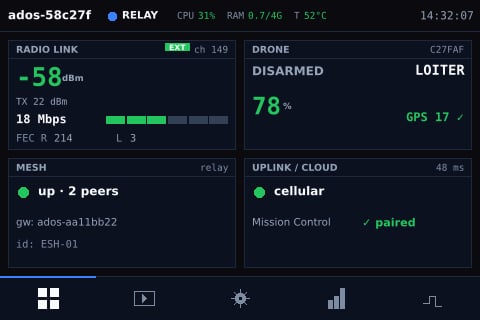
The LCD dashboard: Radio link, Drone, Mesh and Uplink / Cloud tiles, with the tab bar at the bottom.
OLED status display
The I2C OLED shows one status frame, refreshed every 2 seconds from the agent’s ground-station status:- The hostname.
- The LAN IP address.
- The link:
link: idlebefore a drone is heard, thenlink <state> <rssi>dBm. - The status:
PAIRING <n>swhile a mesh accept window is open, otherwiserole: <role>, thenuplink uporready.
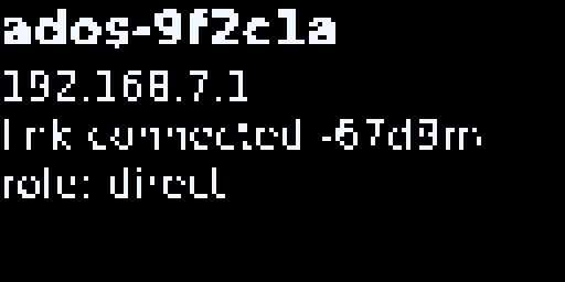
The I2C OLED status frame on a direct-role ground station with a linked drone.
Wiring and detection
Wire SDA, SCL, VCC (3.3 V) and GND to the board’s I2C bus 1. On a Raspberry Pi the installer enables I2C; reboot once after the install so the bus appears. The service starts only when/dev/i2c-1 exists, then probes address 0x3C and then 0x3D. With no panel answering, it exits cleanly.
Settings
Set these in/etc/ados/env and run sudo systemctl restart ados-oled-i2c:
Brightness is
ground_station.ui.oled.brightness (0 to 255, default 204), applied as the panel contrast whenever it changes. Set it with PUT /api/v1/ground-station/ui/oled.
Buttons
Four momentary buttons drive the touch LCD. A press is short or long: a long press is held at least 2 seconds and fires on release; holding 6 seconds or more cancels the press.
These are the fallback pins. A board profile can declare its own pins in a
buttons block (up, down, select, back), which the installer writes into the board record at /run/ados/board.json; the four pins map in that order to B1 to B4. The Raspberry Pi 3 and 4B profiles use the pins above.
Remap the buttons
Remaps are stored inground_station.ui.buttons.mapping and written from Mission Control (node panel, Buttons) or with PUT /api/v1/ground-station/ui/buttons. The keys are B1_short, B1_long through B4_long. The panel acts on these eight actions:
Any other action name does nothing.
Touch display (SPI LCD)
The LCD is drawn by the nativeados-display renderer under the ados-oled unit.
Auto-provisioning
1
Detect
The board’s hardware profile lists its supported displays. With
--display auto (the ground-station default) the installer picks the panel the board declares; --display <id> selects one explicitly and --display none opts out.2
Provision
The installer enables the display overlay and the kernel modules, and records the framebuffer, rotation and panel in
/etc/ados/display.conf.3
Bind
After the reboot the renderer finds the framebuffer and the touch input attaches. If the panel never binds, the installer’s probe restores the previous boot configuration. If the touch controller is missing when the renderer starts, or drops out later, the renderer keeps looking for it every 500 ms, so a late-loading driver or a re-seated panel gets touch back without a restart.
Pages
A bottom tab bar holds five tabs: Dashboard, Video, Settings, Link stats and Channel hops. The top bar shows the hostname, the role, CPU, RAM and temperature, and the clock. The dashboard has four tiles. Tap one to open its detail page:- Radio link: signal, rate and FEC counters. Shows Hardware while no radio adapter is found.
- Drone: the paired drone. Shows Pair drone while no drone has been heard.
- Mesh: role, peers and gateway. Shows Setup wizard while setup is not finished or the role is unset, and MESH N/A on a direct node that cannot join a mesh.
- Uplink / Cloud: the active uplink and cloud reachability.
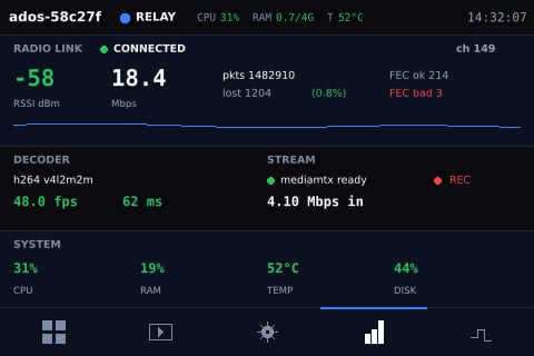
The Link stats tab: radio signal with its RSSI trend, bitrate, packet and FEC counters, and the decoder and system bands.
Mesh detail page
Tap the Mesh tile to open the mesh detail page. It shows the active role, then one of three bodies: a notice on a direct node, a “mesh down” notice while the mesh forms, or the list of peers. The footer shows the selected gateway and a partition badge.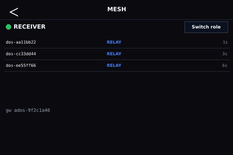
The Mesh detail page on a receiver: role, peer list and gateway footer.
PUT /api/v1/ground-station/role. Mesh pairing itself runs from Mission Control or REST; see Build a mesh.
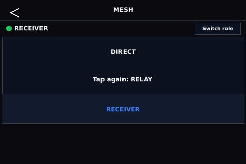
The role picker with RELAY armed, waiting for the confirming tap.
Touch gestures
Calibration
Touch calibration is a nine-point (3x3) capture. It runs from the setup wizard’s Local display step, from Mission Control (node panel, Display), or from the Calibration page on the panel. Results persist across reboots.Supported boards
The Raspberry Pi 4B and the ROCK 5C Lite also support an alternative wiring: an 800x480 HDMI panel with an XPT2046 resistive touch layer on SPI. A rig uses one wiring or the other. The touch layer is calibrated with the same nine-point capture.
A new board adds a
displays block to its hardware profile; see HAL and tiers.
Mission Control mirror
The Display tab of the ground station’s node panel in Mission Control mirrors the panel: type, controller, resolution, rotation, last-touch age, the current page and the calibration state, with a live page preview. You can switch pages and start calibration from there. The Buttons tab holds the button mapping and Bluetooth gamepad pairing. See Ground station node panel.Graceful degradation
Every part of the front panel is optional. With no OLED, its service exits cleanly. With no LCD, the renderer does not start. The dashboard, the cockpit and Mission Control still expose every setting.Next steps
HDMI kiosk
The cockpit on an HDMI monitor.
Build a mesh
Roles, pairing and the mesh page in use.