Calibration Types
Mission Control supports 9 calibration types for ArduPilot and PX4. Not all types apply to every vehicle or firmware.Calibration Wizard
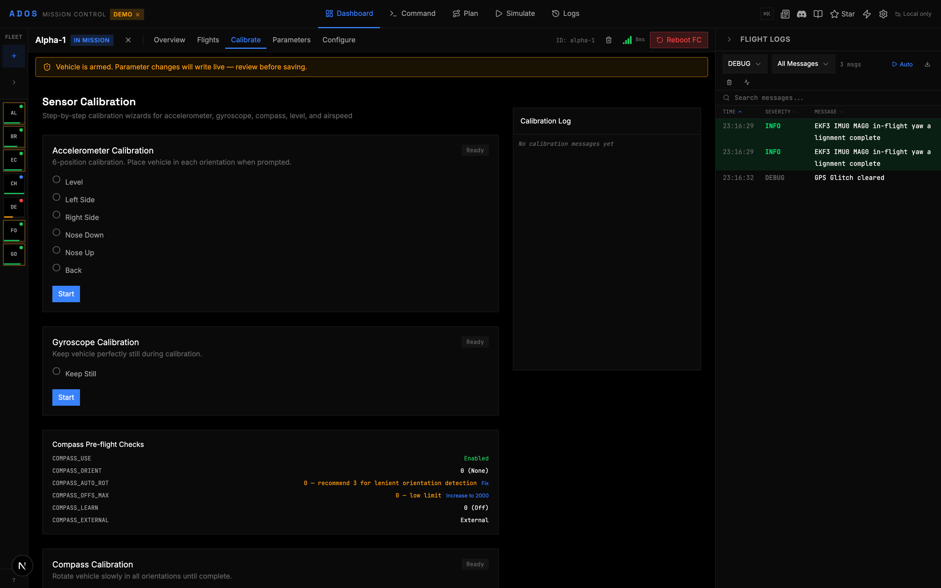
Each calibration type uses a step-by-step wizard:1
Select calibration type
Open the Calibration panel from the Configure section. Choose the calibration you want to perform.
2
Follow position instructions
For multi-position calibrations (accelerometer, compass), the wizard tells you which orientation to hold. For example: level, left side down, right side down, nose down, nose up, on its back.
3
Wait for data collection
Hold the vehicle still in the requested position. The progress bar fills as the FC collects samples.
4
Move to next position
When the current position is complete, the wizard advances to the next step. Repeat until all positions are done.
5
Review results
The wizard shows success or failure. For compass calibration, per-compass fitness values and orientation results are displayed.
Accelerometer Calibration
The accelerometer calibration uses 6 positions:- Level - Place the vehicle flat on a level surface
- Left side - Tilt so the left side faces down
- Right side - Tilt so the right side faces down
- Nose down - Tilt forward so the nose points down
- Nose up - Tilt back so the nose points up
- On its back - Flip the vehicle upside down
Compass Calibration
Compass calibration is the most involved process. You rotate the vehicle in all orientations while the FC collects magnetic field readings. What the wizard shows:- Per-compass progress (% complete) for each magnetometer
- Compass direction vectors in real time
- Completion mask showing which orientation sectors have been sampled
- Fitness score after calibration (lower is better)
- Old vs new orientation if the compass orientation changed
- Start the calibration from the wizard.
- Pick up the vehicle and slowly rotate it in all directions. Tilt, spin, and yaw to cover every orientation.
- Watch the progress bars. When all compasses reach 100%, the calibration completes automatically.
- Review the fitness scores. Fitness below 20 is good. Above 50 suggests magnetic interference.
RC Calibration
RC calibration maps your transmitter’s stick ranges to the FC’s expected input range.1
Start RC calibration
Select RC Calibration in the wizard. Make sure your transmitter is bound and connected.
2
Move all sticks to extremes
Move each stick to its full range in all directions. The channel bars show the min, center, and max values for each channel.
3
Center all sticks
Return all sticks to their center positions. The wizard records the center values.
4
Complete
The wizard writes the calibrated values to the FC. Channel ranges are now set.
ESC Calibration
ESC calibration sets the throttle range so all ESCs respond identically to the same throttle command.- Start ESC calibration from the wizard.
- The FC sends the maximum throttle signal, then the minimum signal.
- ESCs learn the range and beep to confirm.
- The process completes in about 10 seconds.
CompassMot
CompassMot measures how much magnetic interference the motors and power wiring create at the compass location.- Start CompassMot from the wizard.
- The FC slowly ramps up throttle while recording compass readings.
- The result is a percentage: 0% means no interference, 100% means the compass is unusable at full throttle.
- Below 30% is acceptable. Above 30%, consider relocating the compass farther from power lines and motors.
Calibration Log
During calibration, a log panel shows real-time messages from the FC:- Status messages with progress updates
- Warning messages for issues (e.g., “Sample not level enough”)
- Error messages for calibration failures
- Keyword matching highlights important messages
Reboot Banner
Some calibrations require a flight controller reboot to apply the new values. When this is the case, a persistent banner appears at the top of the panel with a “Reboot” button. You can also reboot by power-cycling the FC.Preflight Checks
The Pre-Arm Checks section shows whether calibration is current:- Green: Sensors calibrated and healthy
- Yellow: Calibration may be stale or marginal
- Red: Calibration required before arming