

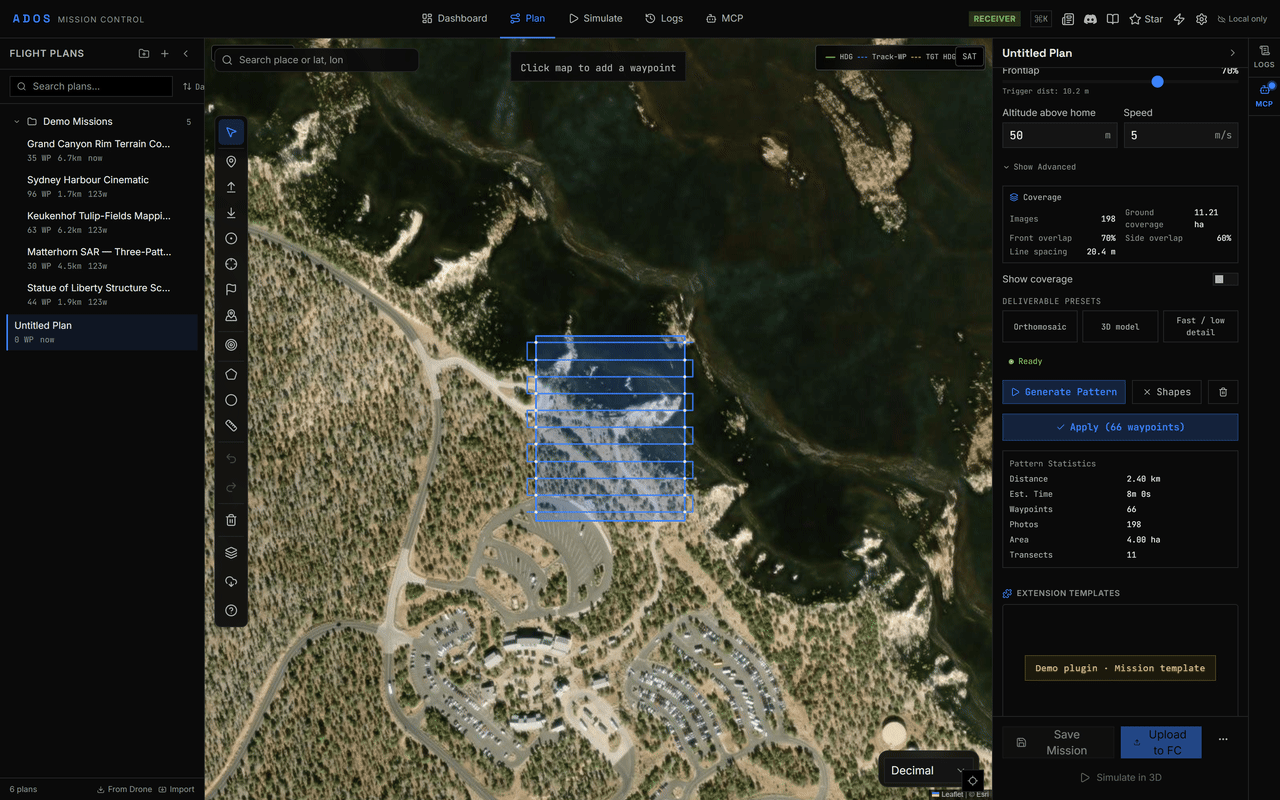
Flight Patterns with a Survey Grid configured from a camera profile, ready to apply.
Generate a pattern
1
Open a plan
Open or create a plan in the Plan tab. See Mission planning.
2
Open Flight Patterns
Expand Flight Patterns in the right panel, or press
G.3
Pick a pattern type
Choose a Pattern Type. The section tells you what it needs on the map: a polygon (Survey Grid, Structure Scan, Perimeter), a circle (Orbit), path points (Corridor), a start point (Parallel Track), a datum point (Expanding Square, Sector Search) or a landing point (landings).
4
Draw and configure
Draw the shape with the Polygon (
P) or Circle (C) tool, or place the point, then set the parameters below.5
Generate and apply
Click Generate Pattern. The preview and its statistics (distance, estimated time, waypoints, and for area patterns photos, area and transects) appear. Click Apply (N waypoints) to add the waypoints to the mission.
relative altitude frame (altitude above home) unless a parameter says otherwise.
Generation limits
Every generator rejects a configuration that would produce an unbounded amount of work and shows the reason in the section instead of a preview:Pattern types
Survey Grid
Parallel transects (a lawnmower pattern) over a polygon, for mapping and photogrammetry.
Pick a camera profile (or Manual) to size the line spacing and trigger distance from overlap. Deliverable presets set the overlap in one click: Orthomosaic (70/70), 3D model (80/80) and Fast / low detail (60/60). Survey presets such as Photogrammetry Standard, High Detail, Quick Overview, Inspection and Magnetic Survey (tie lines on) also set altitude and speed.
Orbit
A circle around a point of interest.Corridor
Perpendicular transects along a path, for roads, pipelines and power lines.Perimeter
One closed loop around a boundary polygon, for fence lines and site edges.Structure Scan
Stacked orbits around a building, tower or similar structure.Search and rescue
- SAR: Expanding Square
- SAR: Sector Search
- SAR: Parallel Track
Legs that spiral outward from a datum (the last known position).Parameters: centre, leg spacing, maximum legs, altitude, speed, start bearing.
Fixed-Wing Landing
A straight-in approach and landing.VTOL Landing
A cruise approach, transition and vertical landing.GSD calculator
For camera patterns, the calculator works from the camera’s sensor width and height (mm), focal length (mm) and image size (pixels), plus the flight altitude. It returns:- Ground sample distance (cm per pixel)
- Image footprint on the ground
- Line spacing for the chosen side overlap
- Trigger distance for the chosen front overlap
Next steps
Geofences and rally points
Fence the survey area and add rally points.
3D mission preview
Check the generated path in 3D before upload.